Design 3 - Vortex Control Adjustment Procedure
- Close Blades and mark closed position on one or two blades in inlet ring to show direction of overlap.
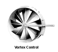
- Remove Vortex Control from fan and lay on work surface with the blades in the closed position, with air leaving side up.
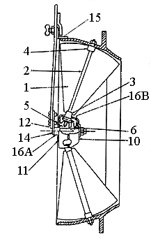
- Remove nut and washer from center shaft (Item 16a).
- Remove Gear Cover Back (item 10).
- Tap center shaft through drive gear (item 6) far enough to allow clearance between gear teeth when drive gear is lifted clear of Bevel Pinions (item 3).
- With a stiff bristle brush and solvent, wash out all of the old grease and dirt.
- Set all blades (item 1) in closed position as marked in step 1, making sure the operating lever is in the proper (closed) position in relation to quadrant on fan. Check for correct rotation; air should enter the Vortex Control in the direction of fan wheel rotation.
- After all blades are set, pack drive gear teeth (item 6) and Bevel Pinion teeth (item 3) with Mobil Synthetic Lubricating grease (Mobilith SCH-PM) or equivalent. Packing the grease solidly around all gear teeth will prevent dust and foreign particles in the air stream from building up between gear surfaces and making operation difficult.
- Tap the Drive Gear (item 6) back on Center Shaft (item 16a) until teeth mesh with Bevel Pinion teeth (item 3).
- Test operation by moving operating lever (item 12).
- Reinstall Gear Cover Back (item 10), washer, lock washer, and nut. Tighten nut. Prick punch between threads of center shaft (item 16a) at the nut to prevent nut from backing off. Thread Lock could also be used.
- Reinstall Vortex Control Assembly in origional Position on fan, tightening all fastners securely. Open and close Blades with Operating Lever several times to work in grease and make certain of proper operation. Reconnect Lever to operating mechanism, of if manually operated, set Operating Lever in customary open position on Quadrant by means of thumb screw.
 Vortex Inlet Damper

